Hughes and Kettner Micro Distortion Valve Amps
  • Home
    • Contact Us
    • Low Watt Valve Guitar Amps
  • Cream Machine
  • Metal Master / Metal Shredder
  • BATT / Bass Master
  • Blues Master / Crunch Master
Share

Overview

The Metal Master with gain dialed up produces a heavy metal guitar tone typical of Led Zepplin, Deep Purple and Black Sabbath.

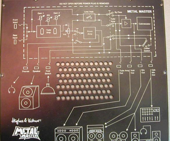
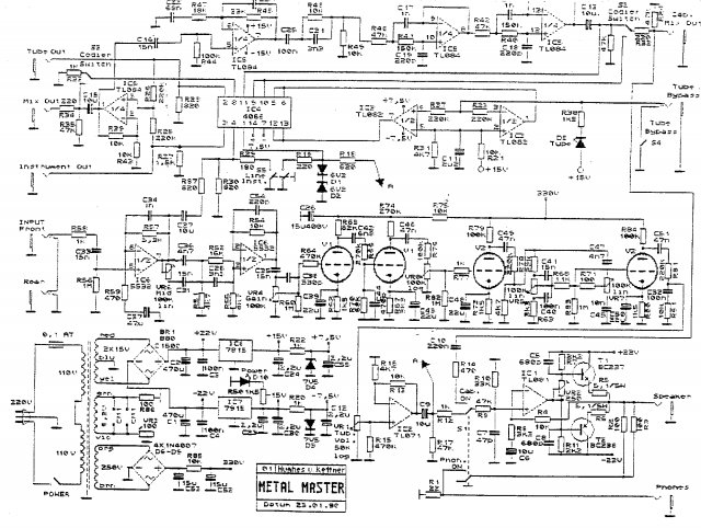
Despite the name, this mini amp can produce a warm clean sound when set to lower gain levels and the tone can be varied widely with its effective EQ. When desired it will blare out 1980s style screaming metal with the gain turned up. Overall it makes a great head for practice amp or recording DI or as an effect unit in a pedal chain.  The 

Metal Master is the same form factor as the other
Hughes & Kettner "Sound Machine" low power amps. It  is equipped with two 12AX7 (ECC83) valves in the pre-amp, 3 EQ bands and a 4.5W solid-state power amp, which drives speakers through the speaker output. As can be seen in the photo at the right, it is has a wide range of output jacks. These include: tube amp out, instrument out, mix out, cabinetular out (similar in function to a H & K RedBox) and speaker out. It even contains a switchable headphone jack, which makes the unit ideal as a fully featured amp for for quiet practice. Certainly better than those "toy like" practice amps currently available.

Schematic

hughes-kettner-metal-master-schematic-big.gif
File Size: 106 kb
File Type: gif
Download File

Manual

metal_master_manual.pdf
File Size: 22 kb
File Type: pdf
Download File

Sound Samples

mm1_-_sample.mp2
File Size: 33 kb
File Type: mp2
Download File

mm2_-_sample.mp2
File Size: 20 kb
File Type: mp2
Download File

Specifications

Preamplifier tubes
  • 2 x 12AX7 preamp tubes
Power Amplifer
4.5W solid-state output transformer
120V AC and 240V / 220V versions

1. Input
  • Input jack for electric guitar
2. Gain 1
  • Gain attenuator to control first stage pre-amp gain
A / B / C equalisation (Treble / Mid / Bass)
Bright switch
3. Bypass
  • Displays state of the bypass switch
  • On = Tube circuit
4. Gain 2
  • Gain attenuator to control second stage pre-amp 
5. Power
  • Mains switch
6. Power indicator LED
7. Fuse
  • 0.1W Slo-blo
8. Mains cord
9. Speaker
  • Speaker power output is 4.5W - 8 Ohm
10. Tube Amp Switch Position 
  • Crunch Master Signal
        Bypass Switch Position
  • Instrument Signal is on Line/lnstr. Outputs
11. Footswitch
  • A Standard footswitch plugged into this socket fulfills the same function as Tube Amp / Bypass switch (10).
12. Tube Amp Volume
  • Controls the output power of the tube stage
  • Operates on the Speaker Out signal
13. Tube Amp Out
  • Only Tube Amp signal is available
  • Produces no signal in with switch set to Bypass position
14. Instr Out
  • Only instrument signal
  • Produces no signal at [Instr Out] with switch set to                                 Tube Amp position
15. Line / Instrument
  • Switches the outputs 13, 14, 16 and 17 to                                                    Line or Instrument level       
Output to:                      Switch Position
       Guitar amp input      Instrument
       Power amp                  Line
      Tape machine             Line
      Mixing desk                 Line or instrument      
     Stereo system             Line
16. Mix Out
  •   Either Tube or Bypass signal is available
17. Cabinetulator Mix Out
  •  Same as Mix Out with added 4 x 12” Celestion
18. Input
  •  Rear Input jack
  • When used the front input is switched off
19. Headphone Jack
20. Headphone On / Off Switch 


AC/DC Song Played through a Metal Master

Picture
Picture

Back View

Picture
Picture


Switch Settings

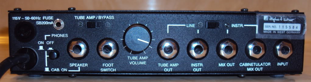
The controls, switches, jacks etc. of the Metal Shredder (U.S. name)/Metal Master (European name) are nearly identical to those of the Cream Machine and Blues Master/Crunch Master. The instructions for using the Metal Shredder/Metal Master are therefore the same, with the following exceptions:

  • The Metal Shredder/Metal Master utilizes a two-stage tube preamplifier. The two stages can be controlled separately by means of the GAIN 1 and GAIN 2 knobs.
  • An infinite number of sound combinations can be attained depending on the relationship between these two knobs, from clean or crunch to heavy overdrive.
  • The MID control takes its place in the signal chain before the tube stages and its main purpose is to adapt to the characteristics of the guitar and pickups.
  • To avoid undesirable distortion in the bass or treble range, the BASS and TREBLE controls function in the signal chain after the pre-amp tube stages.
  • There is a separate headphone jack (PHONES), which is turned ON or OFF with a back panel push-button switch.
  • The Phones switch serves a second function as well. At the same time that it switches the headphone jack on, it also applies CABINET SIMULATOR circuitry (like in the Hughes & Kettner Red Box) to the signal appearing at the SPEAKER OUT jack. This will give hi-fi speakers or full-range P.A. speakers connected to this jack the sound character of a guitar loudspeaker. 
  • There is an integral 4½-watt solid-state power amp for connecting a guitar loudspeaker cabinet or – in the manner described above – a hi-fi speaker cabinet. 
  • Warning! If you connect hi-fi or other full-range speakers to the SPEAKER OUT jack, make sure you use the Cabinetulator circuitry by pressing in the red Phones switch, or else you might blow your high-frequency drivers out!
  • The TUBE AMP VOLUME control determines the overall output level of the SPEAKER OUT by varying the output transformer power.  This control has no affect on the Bypass signal. 


Bypass function

As with the Cream Machine and the Blues Master/Crunch Master, the BYPASS output signal will function with or without the Cabinet Simulator circuitry, or switched off. Internal switches are used to set the BYPASS functions between Off or On with no Simulator filtering or ON with Simulator filtering. 

To set the desired BYPASS function to one of the operating three modes, follow the switch setting diagrams below:
Picture

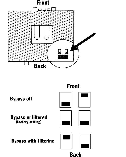
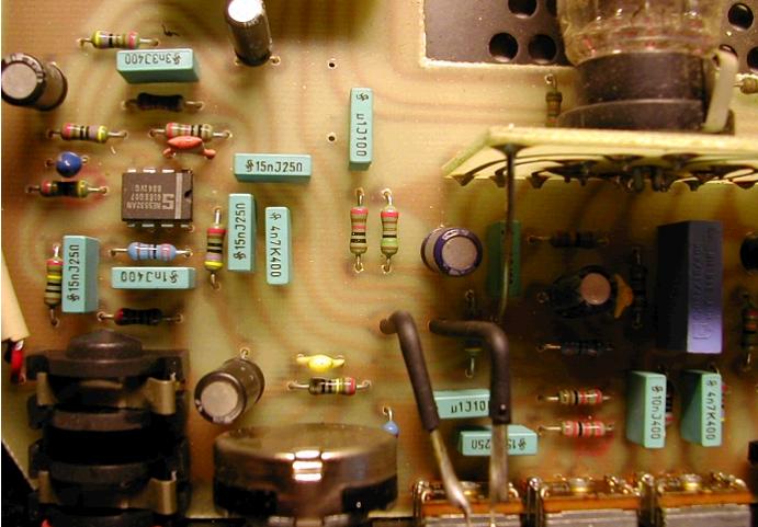
The internal Bypass switches can be seen in the photo below. They are the two red switches with black slides. They are set as per the instructions above.
Picture

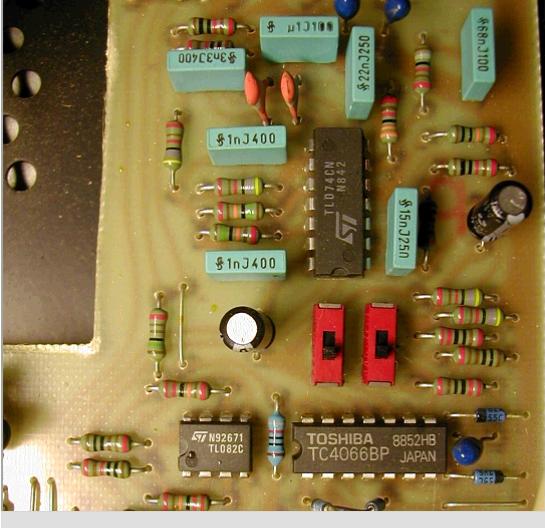
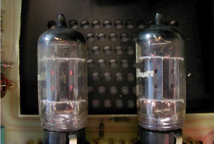
Below can be seen the two 12AX7 valves used in the preamp section. Note the cooling vents under the tubes. It is important not to block the bottom airflow to the vents. 

To the right of the valves is the output transformer. The three large cylinders are high-quality electrolytic capacitors. The upright black and blue jacketed cylinders are smaller electrolytic capacitors.
Picture
Picture
Picture

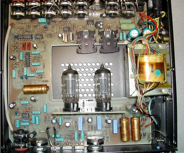
The BD237 (NPN) and BD238  (PNP) are a pair of "sink cooled" medium power transistors. The black potentiometer in between those two components is for setting the bias. The part to the right of the potentiometer is a TL081 JFET op amp, which I am guessing is used to produce distortion. 
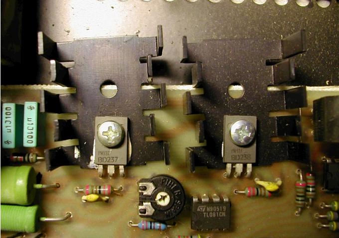
Picture
Create a free website with Weebly